Thin Film Processing Method: from lab to Industrialization of OPV Devices (1st Part)
In comparison with the existing photovoltaic technologies, organic photovoltaic (OPV) is known as a low-cost technology. This is allowed by the fact that organic solar cells (OSCs) could be solution-processed. The main advantage of solution-processing is that OCs could be fabricated at ambient pressure and ambient temperature, reducing manufacturing costs. Over the last decade, the development of new efficient organic materials resulted in power conversion efficiencies (PCE) of organic solar cells (OSCs) exceeding 17% 1,2 at the laboratory scale but the majority of the produced devices have small dimensions and are manufactured by simple laboratory techniques like spin coating (this technique will be detailed in the following paragraphs) which generally wastes large amounts of materials and which allow producing small device series.
To ensure large-scale production of these OPV devices, less wasteful methods compatible with continuous processes must be used. These can be broadly divided into coating techniques, which are suitable from the laboratory scale up to large scale manufacturing, and printing techniques, which are commonly adapted from large scale commercial processes and which have shown their effectiveness in several areas in particular for OPV. In general, the coating is used to describe a process by which a layer of ink is transferred to the substrate by essentially pouring, painting, spraying, casting, or smearing it over the surface. The use of the word printing may also imply that a complex pattern is formed whereas coating generally does not infer this.
The aim of this newsletter is to introduce the reader to the main deposition techniques for the fabrication of OPV devices. As shown in our previous article, OSC is based on various layers. On a lab-scale, some of these layers could be deposited by thermal evaporation under a high vacuum. This technique allows very accurate control of the thickness of the deposited layer as well as low contamination of OSCs allowing to produce high quality of films. However, it is time-consuming and expensive as it is operated under a vacuum. Thus, evaporation is not the most suitable deposition technique and solution-processed OPV cells and modules are often preferred for industrialization. Based on this observation, the next paragraphs focus on the main technics and their specific applications. First, solution-processed technics from lab to fab are presented, prior to describing how these technics could be adapted in a manufacturing line. The working principle of each printing will be illustrated schematically in the corresponding Figure.
First part: Coating techniques widely used in laboratories
The solution processing presented in this section is widely used in laboratories. They allow obtaining quickly OSCs layers with simple ink formulation.
Dip Coating
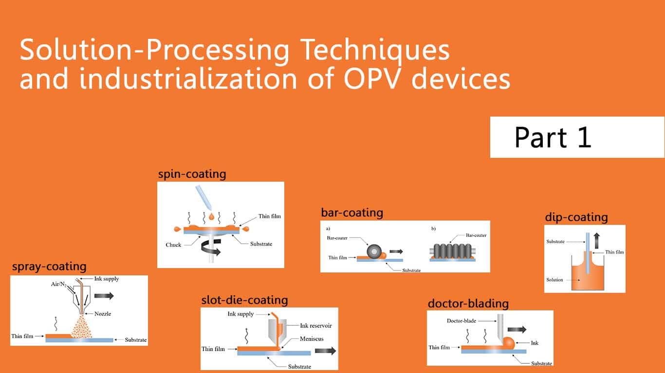
During dip coating, the substrate is immersed in the coating solution. As it is withdrawn, a liquid layer is entrained on the substrate. The thickness of this entrained solution is determined by the withdrawal speed. A wet film with a well-defined thickness is dragged from the liquid upward along with the moving substrate. Despite its simple appearance, the dip-coating process involves a complex interplay between many counteracting factors: viscous drag upward on the liquid by the moving substrate, the force of gravity on the wet film, surface tension in the concavely shaped meniscus, surface tension gradient along with the height of the film due to drying effects, the disjoining (or conjoining) pressure. In general, dip coating requires a very fluid adhesive in the viscosity range of 50–500 mPas. This technique can be adapted to coat different surfaces (such as flat substrates or tubes). But it is very difficult to coat curved or flexible substrates. Several groups have demonstrated that the use dip-coating technology as a fabrication tool allows obtaining efficient OSCs 3,4

Spin Coating
Spin-coating is the most widely used coating technique for OSCs layer deposition on a laboratory-scale during device optimization and materials screening. It involves the deposition of a solution on a substrate and the spinning of this substrate at a chosen rotational speed. 5,6 The centrifugal force shears the solution, causing it to be distributed evenly across the surface as a thin film. The thickness of the deposited film is determined by the shearing force applied, which is proportional to the rate of rotation. It allows for obtaining quickly homogeneous films with high reproducibility in thickness and morphology. This technique is perfect for use in research and development laboratories working on a wide range of thin-film technologies (such as photovoltaics and light-emitting diodes). However, it is a wasteful technic: most of the solution is ejected during spinning. Additionally, this can make it difficult to coat with a low-concentration solution. The main limitations of spin coating are that it is only effective for coating small substrates and is limited to batch processing. Spin coating is completely unsuitable for large-scale production of OPV devices, so this limits its applications to research and development.
It is important to mention that the highest lab efficiency and most of the world record in OPV were achieved using this technique for organic material deposition. 7

Drop Casting
Drop casting is a simple film-forming technique used by many research groups as it does not require specific equipment. The solution containing the desired material is cast on a substrate following by the evaporation of the solvent. However, it is difficult to obtain a uniform layer and to control its thickness (these parameters are fundamental for obtaining performing OPV devices)6,8. This technique is similar to spin coating, but the major difference is that no substrate spinning is required. Also, the film thickness and properties depend on the volume of the dispersion and concentration. Other variables that affect the film structure are substrate wetting, the rate of evaporation, and the drying process. Volatile solvents are generally preferred for this technique which can wet the substrate. One of the advantages of spin coating is less material wastage.

Doctor Blading
For Doctor-blading (also known as blade coating) which is a popular thin-film fabrication technique, a sharp blade is placed at a fixed distance from the substrate surface. The ink formulation is placed in front of the blade. Then the blade is moved linearly across the substrate leaving a wet film that is dried. The final thickness is a fraction of the gap between the substrate and the blade. The final thickness of the wet film will be influenced by the viscoelastic properties of the solution and the speed of coating. In comparison with spin-coating, doctor blading is more material-saving. Moreover, drying conditions are closer to those obtained with industrial processing, allowing to use it for the upscaling of OSCs layer deposition9,10. However, the wet layer film thickness has poor reproducibility. This is due to the shearing rate of the solution impacting the final film thickness. This technique is well suited for large-scale coatings and also well suited for creating thicker films from a viscous solution. It cannot offer the nanoscale uniformity or extremely thin films that spin coating can.

Knife Coating
Knife coating11 as an R2R technique is similar to doctor-blading on a laboratory scale. The layer is deposited at a stationary knife, in front of which an ink reservoir is continuously supplying the meniscus standing between the web and the blade. The web movement ensures the layer deposition as it passes the knife. The wet thickness is related to the gap size between the knife and the substrate and to some extent also to the web speed. As a rule of thumb, the wet thickness is roughly half the gap size. Knife coating is suitable for the deposition of homogeneous layers on large areas and can be carried out at high speed (>10 m/min).

Bar Coating
Bar coating (also known as Meyer bar coating) is very similar to doctor blading. An excess of the solution is placed on the substrate and it is spread across by a bar. This bar is a spiral film applicator and is essentially a long cylindrical bar with wire spiraling around it. The gaps made between the wire and the substrate determine how much solution is allowed through. This subsequently determines film thickness. Coating speed, solution concentration, and bar-substrate distance should be carefully adjusted in order to obtain optimized thin film13. With this technique, the thicknesses of films are limited to the diameter of the wire. This technique is often used in the same fields as blade coating because of the similarities between the coating methods.
Flexible polymer solar cells were successfully demonstrated by optimizing the bar-coating process providing good uniformity of the deposited layers on the reflective bottom electrode.12

Dip coating, drop-casting, spin-coating, bar coating, knife coating, and doctor blading are individual film-forming techniques processing of the small substrate. If doctor blading could be compatible with the manufacturing line, most of these technics do not allow patterning: the whole substrate is covered during processing. Thus, other technics are preferred for industrial production
Spray Coating
Spray-coating is based on sub-micrometric droplets ejection on a substrate. The aerosol is created by passing ink through a nozzle. The path traveled by the nozzle over the wafer is optimized to ensure that the coating is applied evenly to the substrate. The solutions used in spray coating usually feature a very low viscosity, which guarantees that fine droplets form. Spray coating ensures a uniform layer even with high topography substrates, making it the preferred technique for structures of this kind. As techniques described previously, spray-coating coats the whole surface of the substrate. However, it is possible to use masks to pattern the layer. With this technique, the ink waste is not negligible. In particular, spray coating proved to be a valid technique for the realization of organic solar cells 14.

Slot die Coating
Slot-dies coating works pumping the ink through a coating head placed closed to the moving substrate. The solution flows through the head at a determined rate and the substrate is moved underneath it. It is a one-dimensional coating technique, allowing to depose strips of materials with a well-defined width. The exact amount of ink could be a deposit, reducing material waste. One major advantage of this technique is that it is scalable. This means the process would work on an industrial scale. Additionally, it can be used in roll-to-roll processing. These factors make it ideal for use in manufacturing. However, this technique is a significantly more complex process, with multiple parameters needing to be optimized. To create high-quality thin films, a deep understanding of the physics behind each variable is needed. This technique requires more initial training than other techniques. It is a good investment if producing high-volume (when scaling up from development to manufacture) low-cost films but is often too expensive for initial research and development.
Due to its low solution wastage, a wide range of coating viscosities, the high throughput speeds that can be achieved and the possibility for coating one side of rigid or flexible substrates, this technique is used in thin-film electronics especially in organic photovoltaics15, 16.

Although slot die coating is a powerful technique for fabricating OPV modules, its major drawback is that the patterning produced by the coating process is restricted to continuous stripes. In contrast, mechanical printing technologies such as gravure printing, flexography printing, screen printing and offset printing bring the advantage of large-area arbitrary shape and size using only additive process steps in sequence. This increases the freedom of product design and its integration into a range of applications
Click here to find out the second part
Spread the word